Difference between revisions of "3D PRINTING WITH ROBOTS"
| (29 intermediate revisions by one user not shown) | |||
| Line 1: | Line 1: | ||
| − | [[Category: | + | [[Category:Machines]] |
==Material Preparation== | ==Material Preparation== | ||
| − | |||
| − | + | Testing material viscosity and printability before 3D printing is important to ensure good printing outcomes. Here's a breakdown of the recommended process: | |
| − | |||
| − | |||
| − | + | '''Manual Extrusion Test with a Closed Tube Mortar Gun:''' | |
| − | + | ||
| − | + | ||
| − | + | - Use a closed tube mortar gun to manually extrude the material. | |
| − | + | [[File:APLICADOR-MORTERO-ALTA-POTENCIA-TUBO-CERRADO-600-ML-ALYCO-198818PRINCIPAL.jpg| 700 × 402 pixels]]<br><br> | |
| − | + | ||
| − | + | ||
| − | + | ||
| − | + | - This allows you to assess how the material flows and how it behaves during extrusion. | |
| − | + | ||
| − | and | + | |
| − | + | - The closed tube design helps in maintaining consistent pressure and control over the extrusion process. | |
| − | + | '''Mixing the Material:''' | |
| − | + | ||
| − | + | [[File:Mixing Material.png| 700 × 402 pixels]]<br><br> | |
| − | + | ||
| − | + | - Ensure thorough mixing of the material to achieve homogeneity. | |
| − | + | - Inadequate mixing can result in inconsistencies in material properties, affecting print quality. | |
| − | + | - Avoid adding excessive water content, as it can cause shrinkage issues. | |
| − | + | - Conversely, too little water content can lead to dry material, making it difficult to print. | |
| − | + | ||
| − | + | ==Motor screw extruder== | |
| − | + | [[File:Extruder parts 2.jpg| 350 × 201 pixels]]<br><br> | |
| − | + | The Motor screw extruder was originally developed by Eduardo Chamorro Martin in collaboration with 3DPA IAAC. This innovative tool, which is open source, has since been further enhanced and modified by IAAC staff members for various applications. | |
| − | + | For detailed information and updates on the Motor screw extruder, please visit the GitHub repository at the following link: https://github.com/EDUARDOCHAMORRO/FabricatableTools | |
| − | + | ==Printing Steps== | |
| − | |||
| − | 1 | + | '''Step 1: Tool setup''' |
| − | + | - Ensure that all components of the extruder are properly assembled. | |
| − | + | - Mount the End Effector with the Robot Flange securely. Use the appropriate screw size and ensure that the extended parts of the screws do not protrude on the rear side of the flange to prevent scratching or damaging the robot arm. | |
| − | + | [[File:Connector resize a b.jpg| 700 × 402 pixels]]<br><br> | |
| − | |||
| − | + | - Before loading the material into the cartridge, inspect it to ensure there are no air bubbles trapped inside. Air bubbles can disrupt the printing process and cause damage to the print quality. | |
| − | + | - Apply vaseline to the piston and threads in the metal cap of the cartridge. This helps to ensure smooth movement and prevent friction during the printing process. Make sure the cap is tightly secured to avoid any leaks or inconsistencies in printing material flow. | |
| − | + | - Release Pressure Using Pressure Regulator. | |
| − | + | - Connect the air pressure pipe and the motor cable to the designated connector. | |
| − | + | [[File:C connector resize.jpg| 700 × 402 pixels]]<br><br> | |
| − | + | '''Step 2:TCP Calibration''' | |
| − | + | - Calibrate the tool properly. | |
| − | + | - For more details about calibration check the following document | |
| − | + | https://drive.google.com/file/d/196kO1AxNpu0TbMAIdhFcR8AHWfLMZXfV/view | |
| − | + | - Place the TCP value in the gh files | |
| − | + | [[File:Tcp data1-01.png| 700 × 402 pixels]]<br><br> | |
| − | |||
| − | 3 | + | '''Step 3:Extrusion test''' |
| − | + | - Check Digital Outputs Utilize the flex pendant. Use programmable keys on the flex pendant to navigate through the settings and verify that all digital outputs are functioning correctly. | |
| − | + | - Activate the motor and preassure, Gradually adjust the pressure regulator to raise the pressure. Monitor the extrusion process for consistency and quality. | |
| − | + | [[File:Extrusion test.jpg| 700 × 402 pixels]]<br><br> | |
| − | |||
| − | + | '''Step 4:Base calibration''' | |
| − | + | ||
| − | + | - Use masking or double-sided tape to prevent the base from moving. | |
| − | + | - Jog the robot to three different positions. Add Coordinates to Grasshopper File for accurate geometry placement. | |
| − | |||
| − | |||
| − | |||
| − | + | [[File:Bas calbr 23.jpg| 700 × 402 pixels]]<br><br> | |
| − | |||
| − | |||
| − | |||
| − | + | '''Step 5:Export and running the file''' | |
| − | + | IMPORTANT: | |
| − | + | Before running the main file, conduct a pressure-free dry run, execute the file slowly, verify the correctness of the z value, ensure the nozzle doesn't hit the base, and adjust the z value if needed. | |
| − | |||
| − | + | - Check if the robot is in manual mode | |
| − | + | ||
| − | + | - Acknowledge any errors seen on the flexpendant | |
| − | + | - Export your file in .PRG format and copy it in a USB | |
| − | |||
| − | + | [[File:Exportfile.png| 700 × 402 pixels]]<br><br> | |
| − | |||
| − | + | - Plug in the USB in the port on the flexpendant | |
| + | |||
| + | - Go to Main Menu >Production Window >yes >change it to old format (.PRG) | ||
| + | |||
| + | - Select the file and open | ||
| + | |||
| + | [[File:Running a file from usb.jpg| 700 × 402 pixels]]<br><br> | ||
| + | |||
| + | - Check the speed before running the file. | ||
| + | |||
| + | - Press the Guard stop and press the play button to initiate the file | ||
| + | |||
| + | ==Termination of work and cleaning== | ||
| + | |||
| + | |||
| + | - After printing, ensure thorough cleaning of all parts using appropriate cleaning tools. | ||
| + | |||
| + | - Return cleaned parts to their designated places on the shelves. | ||
| + | |||
| + | - Avoid using the sink for cleaning; utilize the large cleaning space designed specifically for clay and concrete materials. | ||
Latest revision as of 18:15, 31 January 2024
Contents
Material Preparation
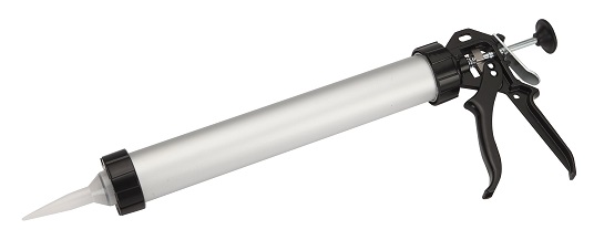
Testing material viscosity and printability before 3D printing is important to ensure good printing outcomes. Here's a breakdown of the recommended process:
Manual Extrusion Test with a Closed Tube Mortar Gun:
- Use a closed tube mortar gun to manually extrude the material.
- This allows you to assess how the material flows and how it behaves during extrusion.
- The closed tube design helps in maintaining consistent pressure and control over the extrusion process.
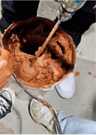
Mixing the Material:
- Ensure thorough mixing of the material to achieve homogeneity.
- Inadequate mixing can result in inconsistencies in material properties, affecting print quality.
- Avoid adding excessive water content, as it can cause shrinkage issues.
- Conversely, too little water content can lead to dry material, making it difficult to print.
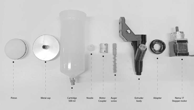
Motor screw extruder
The Motor screw extruder was originally developed by Eduardo Chamorro Martin in collaboration with 3DPA IAAC. This innovative tool, which is open source, has since been further enhanced and modified by IAAC staff members for various applications.
For detailed information and updates on the Motor screw extruder, please visit the GitHub repository at the following link: https://github.com/EDUARDOCHAMORRO/FabricatableTools
Printing Steps
Step 1: Tool setup
- Ensure that all components of the extruder are properly assembled.
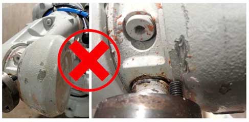
- Mount the End Effector with the Robot Flange securely. Use the appropriate screw size and ensure that the extended parts of the screws do not protrude on the rear side of the flange to prevent scratching or damaging the robot arm.
- Before loading the material into the cartridge, inspect it to ensure there are no air bubbles trapped inside. Air bubbles can disrupt the printing process and cause damage to the print quality.
- Apply vaseline to the piston and threads in the metal cap of the cartridge. This helps to ensure smooth movement and prevent friction during the printing process. Make sure the cap is tightly secured to avoid any leaks or inconsistencies in printing material flow.
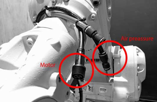
- Release Pressure Using Pressure Regulator.
- Connect the air pressure pipe and the motor cable to the designated connector.
Step 2:TCP Calibration
- Calibrate the tool properly.
- For more details about calibration check the following document
https://drive.google.com/file/d/196kO1AxNpu0TbMAIdhFcR8AHWfLMZXfV/view
- Place the TCP value in the gh files
Step 3:Extrusion test
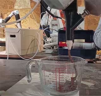
- Check Digital Outputs Utilize the flex pendant. Use programmable keys on the flex pendant to navigate through the settings and verify that all digital outputs are functioning correctly.
- Activate the motor and preassure, Gradually adjust the pressure regulator to raise the pressure. Monitor the extrusion process for consistency and quality.
Step 4:Base calibration
- Use masking or double-sided tape to prevent the base from moving.
- Jog the robot to three different positions. Add Coordinates to Grasshopper File for accurate geometry placement.
Step 5:Export and running the file
IMPORTANT:
Before running the main file, conduct a pressure-free dry run, execute the file slowly, verify the correctness of the z value, ensure the nozzle doesn't hit the base, and adjust the z value if needed.
- Check if the robot is in manual mode
- Acknowledge any errors seen on the flexpendant
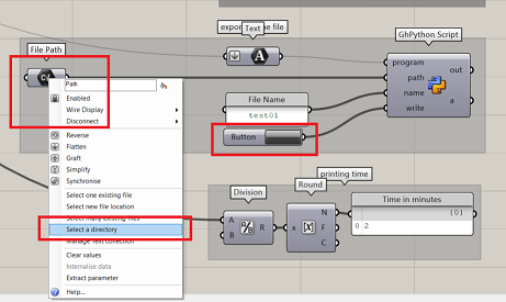
- Export your file in .PRG format and copy it in a USB
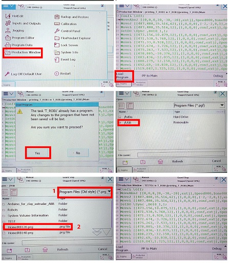
- Plug in the USB in the port on the flexpendant
- Go to Main Menu >Production Window >yes >change it to old format (.PRG)
- Select the file and open
- Check the speed before running the file.
- Press the Guard stop and press the play button to initiate the file
Termination of work and cleaning
- After printing, ensure thorough cleaning of all parts using appropriate cleaning tools.
- Return cleaned parts to their designated places on the shelves.
- Avoid using the sink for cleaning; utilize the large cleaning space designed specifically for clay and concrete materials.
