KUKA PRC
Here you can find a very brief overview of robotic programming with KUKA|prc:
Contents
Robot Programming with Kuka|prc
[All the information explained here is coming from: http://mkmra2.blogspot.com/2016/01/robot-programming-with-kukaprc.html]
KUKA|prc is a set of Grasshopper components that provide Procedural Robot Control for KUKA robots (thus the name PRC). These components are very straightforward to use and it's actually quite easy to program the robots using them.
Rhino File Setup
When you work with the robots using KUKA|prc your units in Rhino must be configured for the Metric system using millimetres. The easiest way to do this is to use the pull-down menus and select File > New... then from the dialogue presented chose "Small Objects - Millimeters" as your template. - Orientation Axes: The other joints (4, 5, 6). These joints are always rotary. Pitch / Roll / Yaw = Orientation Axes. These are the axes closer to the tool.
When installing KUKA|prc has a user interface (UI) much like other Grasshopper plug-ins. The UI consists of the palettes in the KUKA|prc menu.
There are five palettes which organize the components. These are:
01 | Core: The main Core component is here (discussed below). There are also the components for the motion types (linear, spline, etc.).
02 | Virtual Robot: The various KUKA robots are here. This tutorial is mostly be using the KUKA gelis KR6-10 R900 component.
03 | Virtual Tools: Approach and Retract components are here (these determine how the robot should move after a toolpath has completed). There are also components for dividing up curves and surfaces and generating robotic motion based on that division.
04 | Toolpath Utilities: The tools (end effectors) are here. We'll mostly be using the Custom Tool component.
05 | Utilities: The components dealing with input and outputs are stored here. These will be discussed later.
KUKA|prc CORE
The component you always use in every definition is called the Core. It is what generates the KUKA Robot Language (KRL) code that runs on the robot. It also provides the graphical simulation of the robot motion inside Rhino. Everything else gets wired into this component.
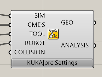
The Core component takes five inputs. These are:
SIM- This is a numeric value. Attach a default slider with values from 0.00 to 1.00 to control the simulation.
CMDS- This is the output of one of the KUKA|prc Command components. For example, a Linear motion command could be wired into this socket.
TOOL- This is the tool (end effector) to use. It gets wired from one of the Tool components available in the Virtual Tools panel. Usually, you'll use the KUKA|prc Custom Tool option and wire in a Mesh component will show the tool geometry in the simulation.
ROBOT - This is the robot to use. The code will be generated for this robot and the simulation will graphically depict this robot. You'll wire in one of the robots from the Virtual Robot panel.
COLLISION - This is an optional series of meshes that define collision geometry. Enable collision checking in the KUKA|prc settings to make use of this. Note that collision checking has a large, negative impact on KUKA|prc performance.
There is two output as well:
GEO: This is the geometry of the robot at the current position - as a set of meshes. You can right-click on this socket and choose Bake to generate a mesh version of the robot for any position in the simulation. You can use this for renderings for example.
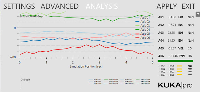
ANALYSIS: This provides a detailed analysis of the simulation values. This has to be enabled for anything to appear. You enable it in the Settings dialogue, Advanced page, Output Analysis Values checkbox. Then use the Analysis component from the Utilities panel. For example, if you wire a Panel component into the Axis Values socket you'll see all the axis values for each command that's run.
Settings
The grey KUKA|prc Settings label at the bottom of the Core component gives you access to its settings. Simply left-click on the label and the dialogue will appear.
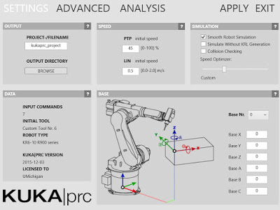
The settings are organized into pages which you select from along the top edge of the dialogue (Settings, Advanced, and Analysis). The dialogue is modeless which means you can operate Rhino while it is open. To see the effect of your changes in the viewport click the Apply button. These settings will be covered in more detail later.
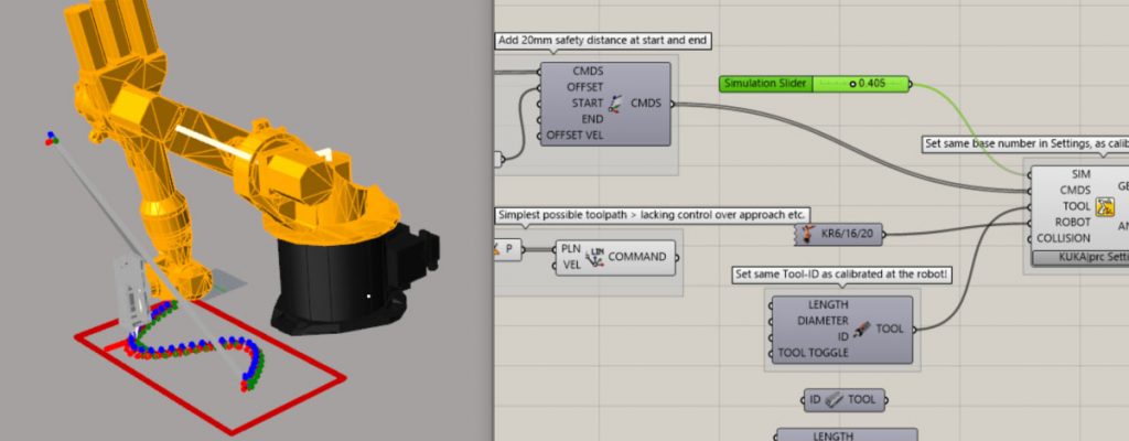
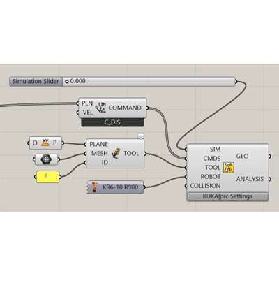
Basic Setup There is a common set of components used in nearly all definitions for use with the robot Workcell. Not surprisingly, these correspond to the inputs on the Core component. Here is a very typical setup:
SIM SLIDER: The simulation Slider goes from 0.000 to 1.000. Dragging it moves the robot through all the motion specified by the Command input. It's often handy to drag the right edge of this slider to make it much wider than the default size. This gives you greater control when you scrub to watch the simulation. You may also want to increase the precision from a single decimal point to several (say 3 or 4). Without that precision, you may not be able to scrub to all the points you want to visualize the motion going through.
You can also add a Play/Pause component. This lets you simulate without dragging the time slider.
CMDS: The components which get wired into the CMDS slot of the Core is really the heart of your definition and will obviously depend on what you are intending the robot to do. In the example above a simple Linear Move, the component is wired in.
TOOL: We normally use custom tools with the robot Workcell. Therefore a Mesh component gets wired into the KUKA|prc Custom Tool component (labelled TOOL above). This gets wired into the TOOL slot of the Core. The Mesh component points to a mesh representation of the tool drawn in the Rhino file. See the section below on Tool orientation and configuration.
ROBOT: The robots we have in this tutorial are KUKA KR6 R900s. So that component is chosen to form the Virtual Robots panel. It gets wired into the ROBOT slot of the Core.
COLLISION: If you want to check for collisions between the robot and the work cell (table) wire in the meshes which represent the work cell. As noted above this has a large negative impact on performance so use this only when necessary.
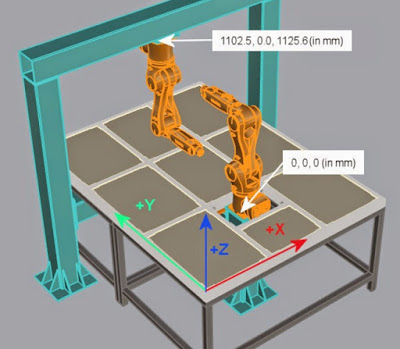
Robot Position and Orientation
These parameters specify the location and orientation of the robot within the workcell 3D model.
Code Output
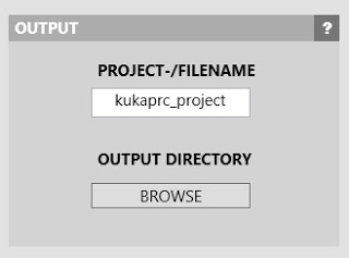
The purpose of KUKA|prc is to generate the code which runs on the robot controller. This code is usually in the Kuka Robot Language (KRL). You need to tell KUKA|prc what directory and file name to use for its code output. Once you've done this, as you make changes in the UI, the output will be re-written as necessary to keep the code up to date with the Grasshopper definition.
To set the output directory and file name follow these steps: Bring up the Settings dialogue via the Core component. On the main Settings page, enter the project filename and choose an output directory. Note: See the? button in the dialogue for recommendations on the filename (which characters to avoid).
Start Position / End Position
When you work with robots there are certain issues you always have to deal with: Reach: Can the robot's arms reach the entire workpiece? Singularities: Will any joint positions result in singularities? (See below for more on this topic) Joint Limits: During the motion of the program will any of the axes hit their limits? One setting which has a major impact on these is the Start Position. The program needs to know how the tool is positioned before the motion starts. This value is VERY important. That's because it establishes an initial placement for the joint limits. Generally, you should choose a start position that doesn't have any of the joints near their rotation limits - otherwise, your programmed path may cause them to hit the joint limit. This is a really common error. Make sure you aren't unintentionally near any of the axes limits. Also, the robot will move from it's current position (wherever that may be) to the start position. It could move right through your workpiece or fixture setup. So make sure you are aware of where the start position is, and make sure there's a clear path from the current position of the robot to the start position. In other words, jog the robot near to the start position to begin. That'll ensure the motion won't hit your set up.
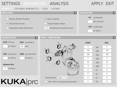
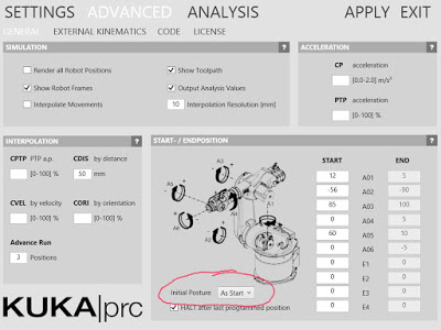
You specify these start and end position values in the Settings of the Core. Bring up the Settings dialogue and choose the Advanced page.
Under the Start / End position section, you enter the axis values for A1 through A6. This begs the questions "how do I know what values to use?".
You can read these directly from the physical robot pendant. That is, you jog the robot into a reasonable start position and read the values from the pendant display. Enter the values into the dialogue. Then do the same for the End values.
You can also use KUKA|prc to visually set a start position and read the axis values to use. To do this you wire in the KUKA|prc Axis component into the Core component. You can "virtually jog" the robot to a specific position using a setup like this:
Then simply read the axis values from your sliders and enter these as the Start Position or End Position.
Another way is to move the simulation to the start point of the path. Then read the axis values from the Analysis output of the Core Settings dialogue. You can see the numbers listed from A01 to A06. Jot these down, one decimal place is fine. Then enter them on the Advanced page.
Initial Posture
Related to the Start Point is the Initial Posture setting. If you've set the Start Position as above and are still seeing motion (like a big shift in one of the axis to reorient) try the As Start option. This sets the initial posture to match the start position.
